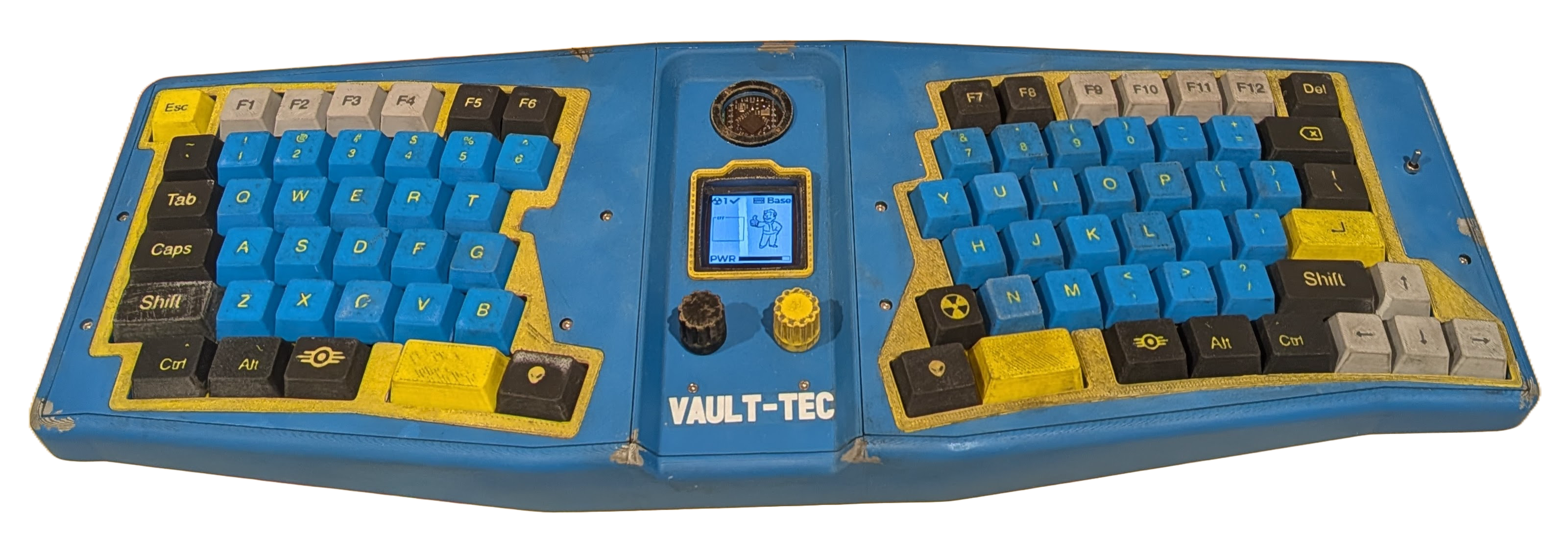
This is the story of a keyboard that’s (supposed to look as though it’s) traveled through radioactive swamps in a nuclear post apocalyptic waste land and been held in the slobbery maw of Mirelurks. The keyboard has 84 keys and the design was loosely inspired by the Pipboy - a kind of cyberpunk wearable from the fallout universe - so I called it the Vault 84.
The story starts back in March when I finished building my second keyboard. I proudly talked about it to friends, family, acquaintances, friends of acquaintances… all of which was met with almost unanimous disinterest. It turns most people really don’t care about keyboards. But it was only almost unanimous disinterest… there were a couple of interested parties.
Firstly, PCBWay read an article about the Paw 34 and they very kindly offered to give me some free PCBs if I ever built another keyboard.
Secondly, a couple of weeks after PCBWay reached out, I was showing the keyboard to my niece and she actually really liked it and she wanted me to build her one 🎊… kind of.
She didn’t want a keyboard like mine… she wanted a “normal one” (with the normal number of keys and everything). Initially this made my heart sink because I didn’t really want to build a normal keyboard. However she did want it to be colourful, which I saw as an opening… and so after trading photos of the kinds of things she might like and a couple of conversations where I tried to persuade her she really wanted something else, eventually we settled on something Fallout themed.
So I would build another keyboard!
Planning the layout
I started by planning the keyboard layout… initially I was thinking of building an Alice layout and that probably would have looked more thematic. But it just looked so damned uncomfortable and I couldn’t bring myself to build something that unergonomic. Eventually I settled on a layout that’s pretty close to what I have on my old Logitech K860 - which is kind of a more curvy version of the Alice layout.
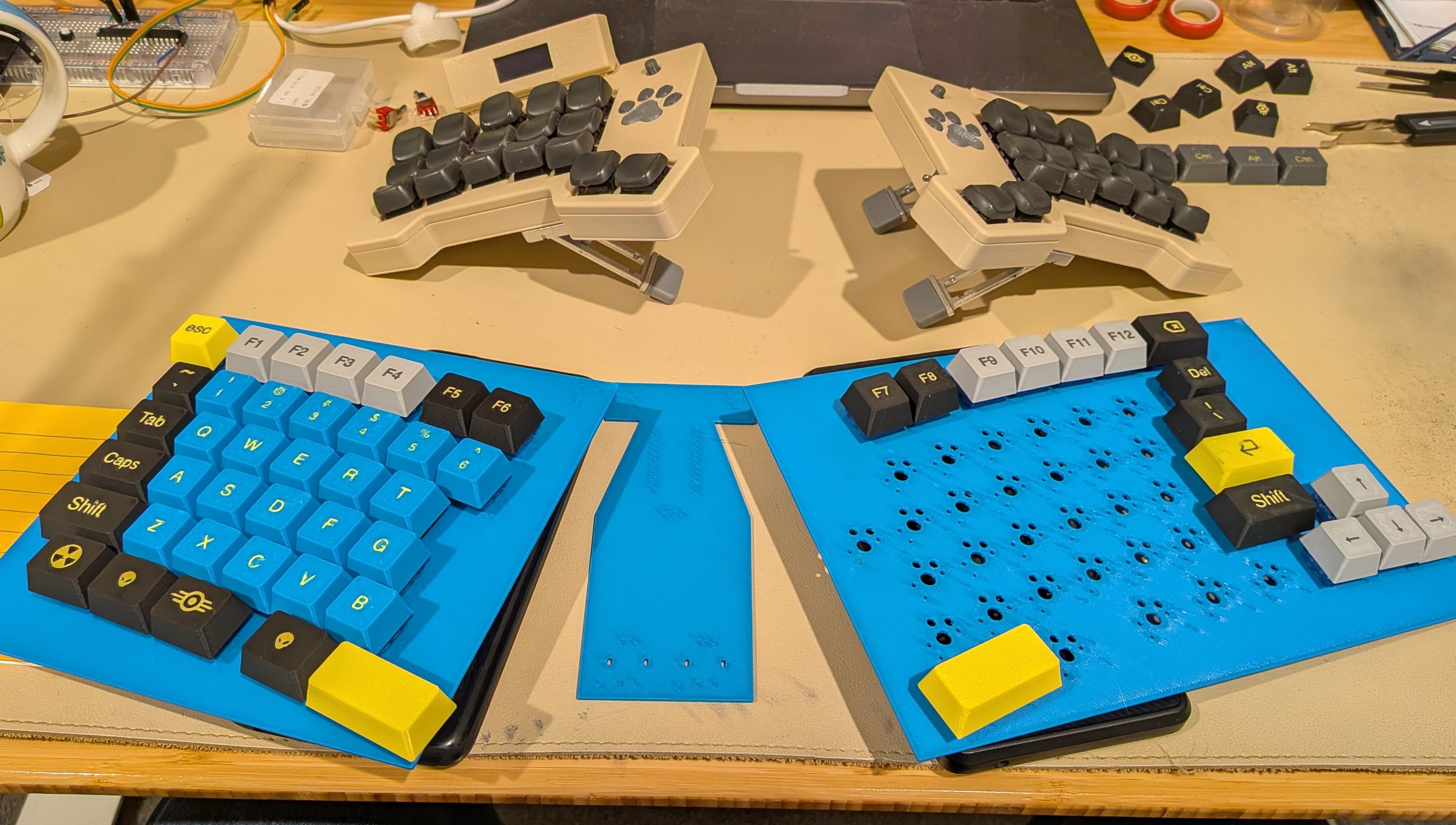
I modeled everything up in KiCad, exported some 3d printable faux-pcbs and plugged some switches and keycaps in to test it out. I say that like it took 10 minutes - actually the math to calculate where to place all the keys to get a staggered curved layout was semi-complex and it took a couple of days to dial it out until I was happy with everything:
Some unique problems…
Having worked out where the keys were going to go, there were a couple of other problems that needed solving for this keyboard. Some because they were necessary for the cool factor that a client of my niece’s calibre demanded (she’s a lawyer so needs a keyboard that makes her look like a trusted pro)… others more as a consequence of the keyboard layout.
Firstly, you’ll note there are 3 PCBs in the above photo… that’s because I wanted a bit of slope on both the left and right hand sides of the keyboard so that the wrists didn’t have to tilt inward as much (your wrists probably want to be at about 45 degrees when you hold your hands out in front of you - they certainly don’t want be at 90 degrees for protracted periods). This meant I had to have either flexible PCBs (technically possible but very expensive) or multiple PCBs connected with either lots of wires or some kind of ribbon cables. I opted for FFC cables… so I needed to solder some FFC sockets onto the PCBs.
Secondly I wanted a couple of ENC11 rotary encoders on the keyboard that could be used to control volume and scroll.
Thirdly, I didn’t have enough pins. The nice!nano2 has 18 easily accessible GPIO pins. The rotary encoders use 2 pins each and the 80% keyboard layout I’d selected had 7 columns and 6 rows - requiring another 13 pins… then I had the OLED which needed another 2 pins for clock and data… all of which is more than 18 pins. After a bit of digging, I discovered shift registers can be used in this situation… basically you send your outbound signals (col signals in a col2row config) as serial signals and the shift registers convert those to parallel signals… so you can have virtually as many pins as you want (certainly at the frequencies used by a keyboard). So, I would need to learn how to use shift registers!
Building the case
With all of the logical problems solved (in theory) I started putting together some very loose ideas for a case that would accommodate the PCBs.
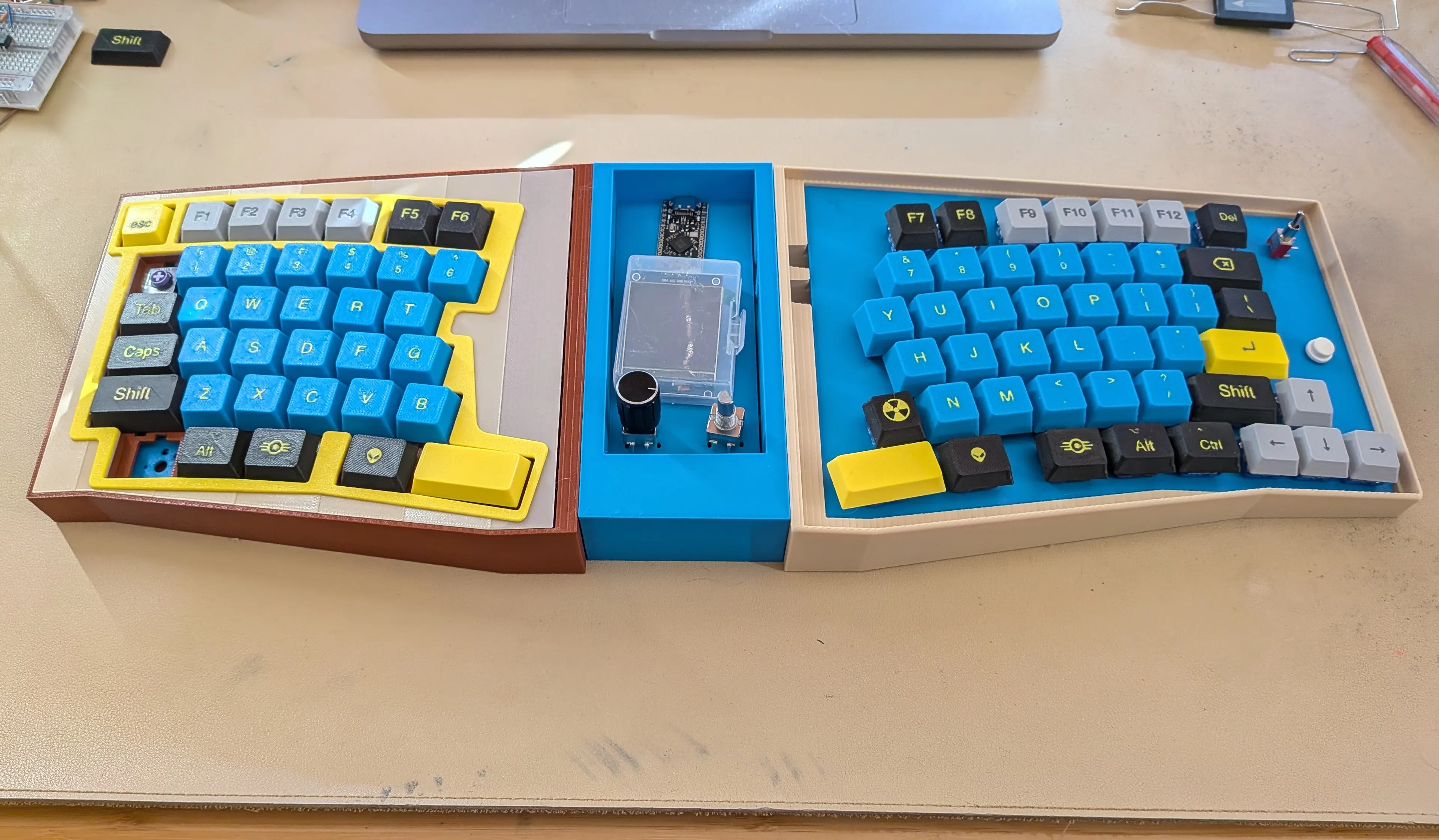
I used Tinkercad and Shapr3d to model my first two keyboards… both of which worked very well. I wanted to try to use Claude to help model the case for this keyboard and neither of those have an MCP server, so for the Vault I used Autodesk Fusion. I’d never used Fusion before so this was a bit of a punt but it turns you don’t need to know how to use 3d software anymore - as long as you can clearly describe what you want either with sketches or words. Claude isn’t as good at conceptualising 3d space as it is at writing code so it definitely requires adult supervision. However ultimately I’m very glad I outsourced all of the modeling grunt work. This meant that I could focus on and iterate on the high level design and quickly pivot away from ideas without regret.
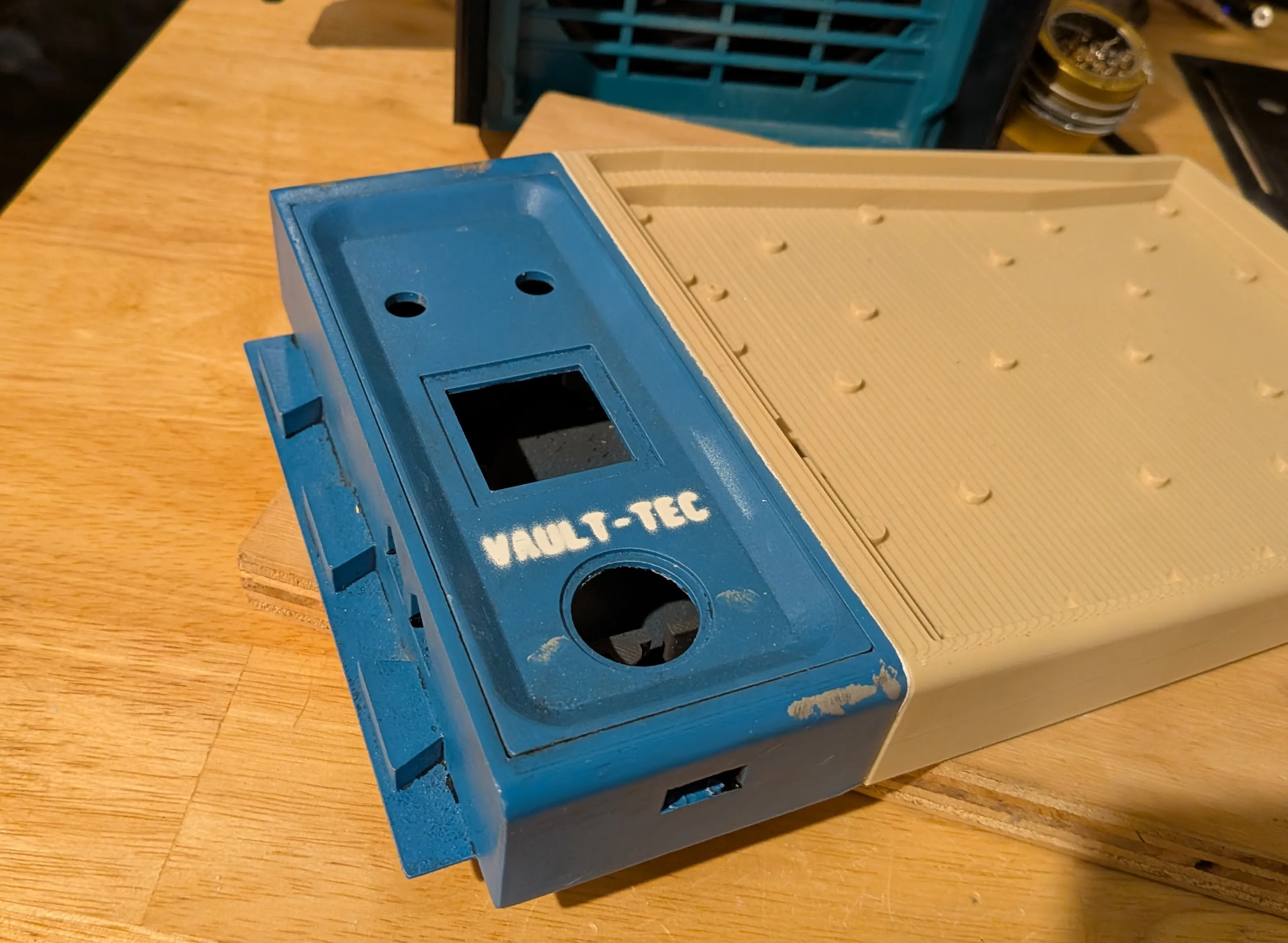
By the middle of August then, I had almost finalised the case design and ran a few tests to make sure it would all hold together and I’d be able to paint it up to look old and ☢️ irradiated.
PCB Day!
Around the end of August I received the PCBs from PCBWay!
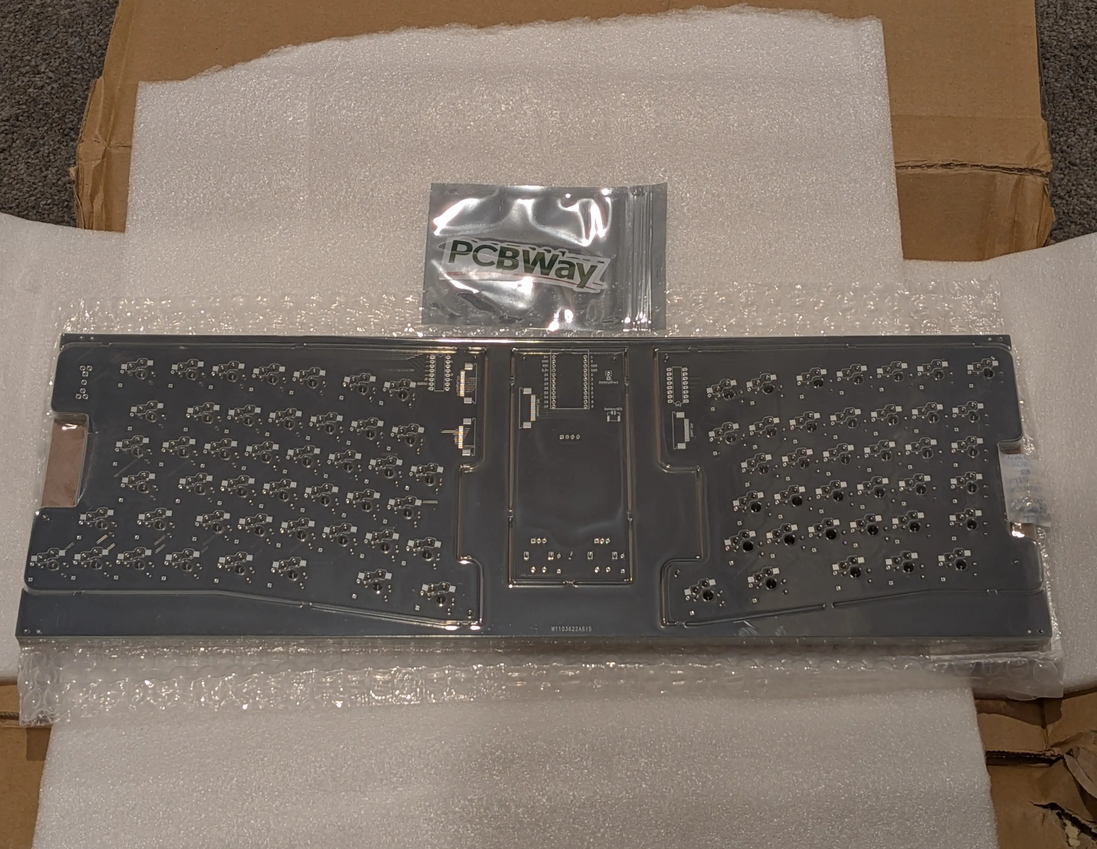
I quickly got to work soldering and checking everything fit in the case and I was super stoked and it was 🤗 really exciting… and also 😔 really depressing.
Exciting, because it looked way cooler than I thought it was going to look. I’d watched some awesome videos by OddViking on YouTube and so, in theory, I knew it was possible to make cool old looking stuff… but I’m not an artist by any stretch of the imagination so I had no idea if I was going to be able to make it look how I imagined it.
Depressing because, it turns out, soldering 1mm FFC sockets is a total pain in the arse. I could usually get one of them working without any bridges - two was a stretch… I struggled to reliably get all of the FFC connectors (4 of them in total) soldered correctly. I also discovered 3 of the 10 nice!nano2 clones in my arsenal were faulty (fused GND and 3V3 pins out of the packet)… let that serve as a warning to anyone buying cheap clones off AliExpress… and lastly I fried one of my 1.5” OLED screens.
The final nail in the coffin was that the key layout wasn’t quite right… some of the keycaps for the 1.5u and 1.75u keys were colliding with their neighbouring keys. Clearly I should have spent a bit more time on the math on day 1 and 2 of this enterprise - which was coming back to bite me now in the home stretch.
So… somewhat deflated, I remodeled the PCBs using surface mounted components for all the diodes and shift registers, tweaked the key layout to address the colliding keycaps and ordered some new PCBs - only this time paying for PCBA (PCB assembly) - meaning I’d receive the PCBs with all of the parts already soldered onto them (and a bunch of fancy continuity and voltage tests would be done to make sure everything actually works).
Finally then, a couple of weeks later, with new PCBs in hand, I pieced everything together and it was done!
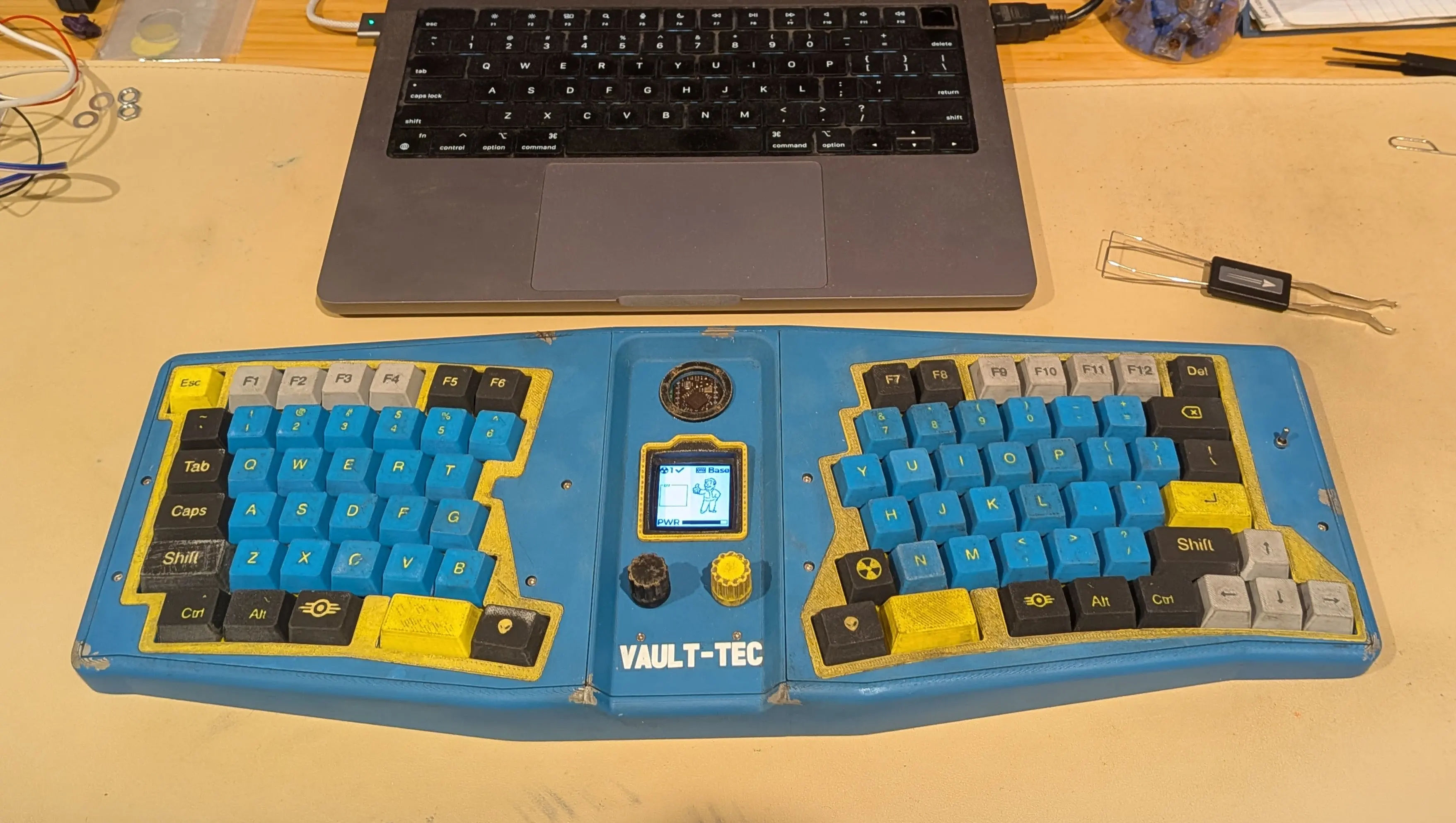
And it probably only took the equivalent of about 2 months full time work and $1000 in parts and shipping 🙃
The night was long and full of terror but it wouldn’t be fun if it was too easy right?
Addendum on the centre console
If you’ve read this far then I assume you’re already an unhealthy way down the rabbit hole and you need some more information on some of the components you will have noticed in the pics above. In particular, there are a few interesting things in the centre console:
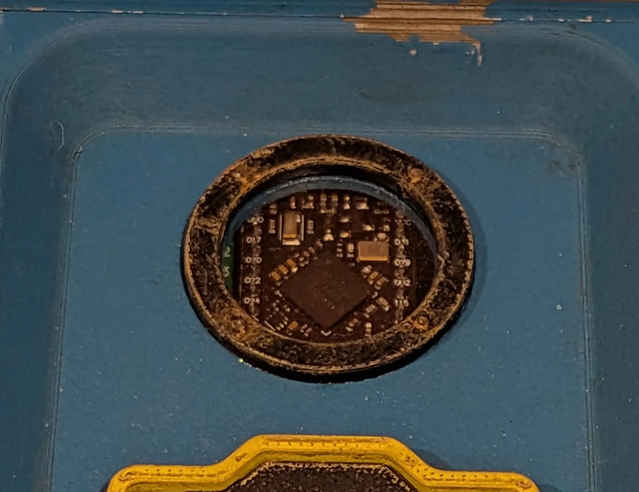
At the top of the console is a small porthole that provides a window through to the brains of the keyboard - the nice!nano2. That's mostly just to add a bit of cyberpunk-ish flare but it does have one practical upside, which is that you can see the indicator lights on the module, which flash red when connected to USB but no connection to the battery can be found and glow solid red when the USB cable is connected and the battery is charging.
Below that is a 1.5" OLED screen with some custom stuff going on. There's the Vault Boy offering his encouragement. The radiation symbol indicates bluetooth connectivity and the `EFF` box shows which modifiers are active.
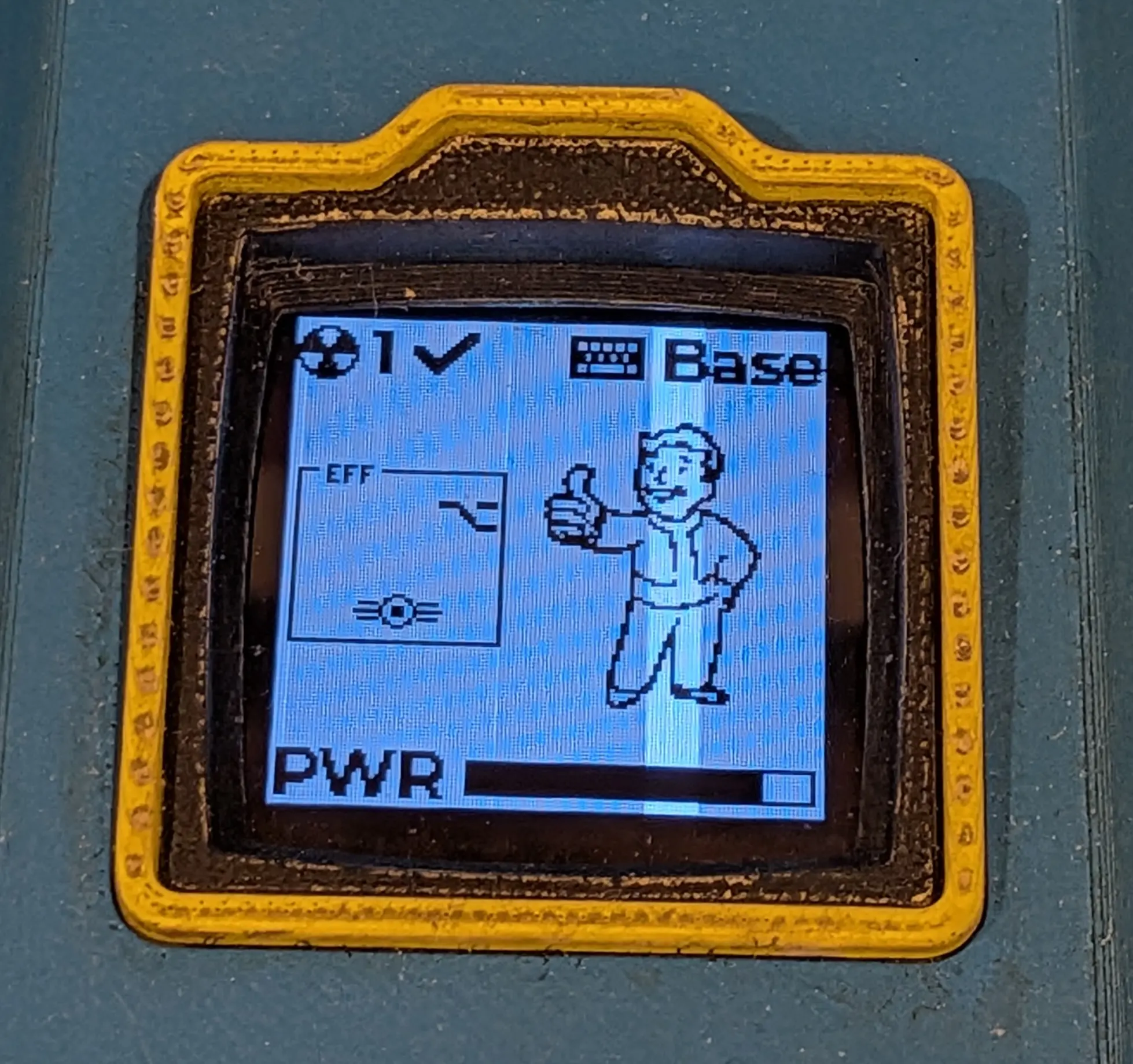
If capslock is on then the Vault Boy image changes to show a strong Vault Boy (similar to what you'd see for the strength perk on a PipBoy in the game).
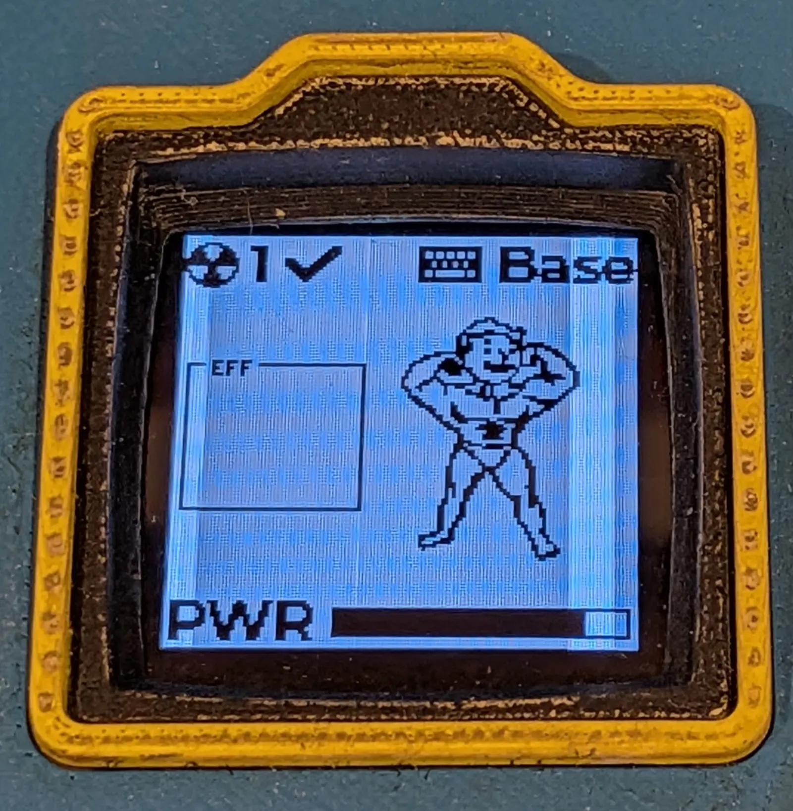
And of course there are the usual features, showing the amount of remaining
battery (PWR) and the active keyboard layer at the top right. I tried to
switch the layer icon out for a map or something but couldn’t find anything
satisfactory, so that remains one of the few un-tweaked parts of the
interface.
Overall I’m pretty happy with how it turned out and I hope my niece really likes it (she hasn’t seen it yet)!
I do, of course, have lots of ideas for improvement - I think I’ll probably make a split version with a few less keys for myself… and I’ll definitely be making some more old looking stuff in future since that side of things was really fun. 😛